| ||||
| ||||
| Moderated by: Greg Fletcher |
|
||||||||||||||
| Starter Solenoid | Rate Topic |
| Author | Post |
|---|
| Posted: 02-06-2016 10:24 am |
|
1st Post |
|
NigelK Member
|
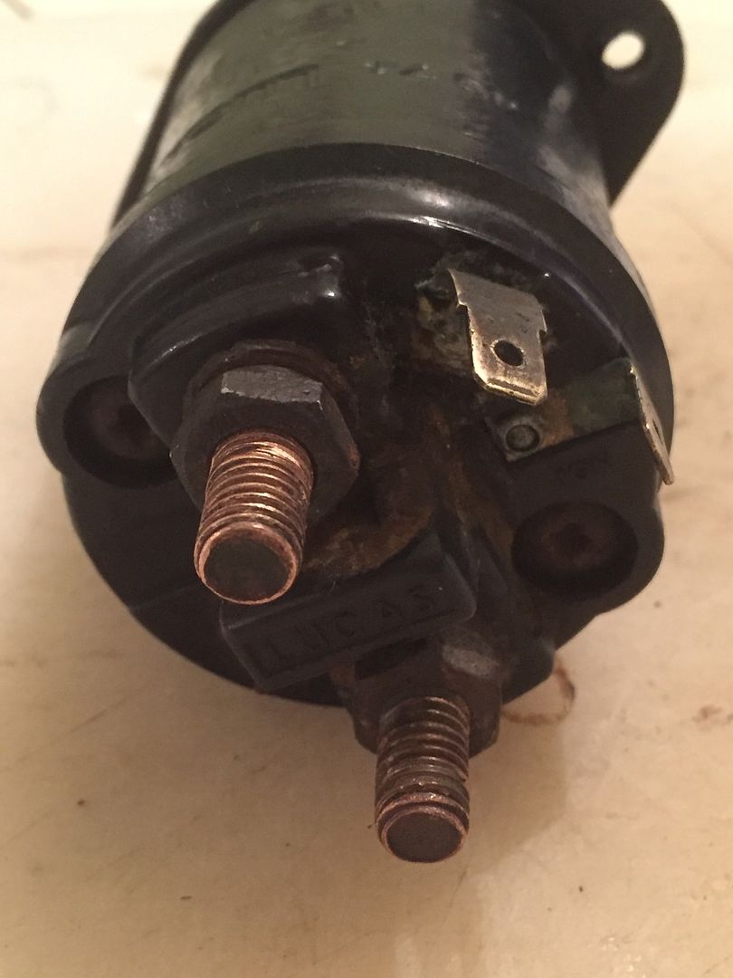
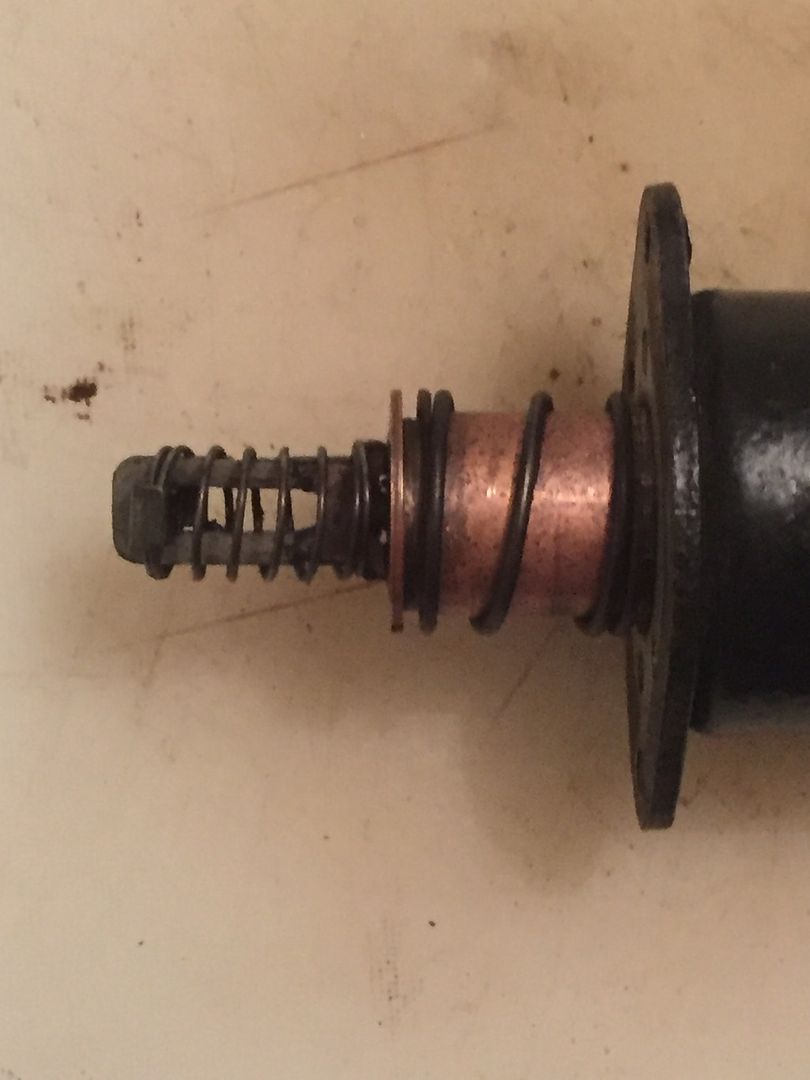
Dear Forum Users I have been temporarily defeated by the starter solenoid. At least, that's what I think has defeated me. Allow me to explain... I fitted new headlight units, and relays yesterday. All went well, but note I took the +ve feed for the headlights off the +ve battery feed post terminal on the starter solenoid (on the left in the image below), which meant undoing the securing bolts so I could put the relay ring terminal on the terminal. The headlights work fine. But when I tried to start the engine to test the improvement in voltage loss in the headlight circuitry, nothing. No click, to whir of the starter motor, and certainly no cranking of the engine. So I pulled the starter solenoid and tested it. No continuity between any of the terminals, apart from about an ohm between the -ve / starter motor post terminal (on the right in the image below) and the larger diagonal spade terminal (top left in the image below). It seems to me that there should be continuity between the +ve battery feed post terminal and the larger diagonal spade terminal, as the former provides the +ve feed to the coil resistor which retracts the solenoid piston when energised and the latter is the earth for this resistor coil?  Getting the solenoid back onto the starter motor was a pig, I cannot see an easy way of retracting the spring so that the "eye" at the end can slide over the lever that points upwards in the solenoid housing and which presumably engages the starter motor crank with the flywheel when the solenoid is activated (see image below). Is there a knack to this?  I've tested all the other parts of the solenoid circuit - there is good voltage to the +ve battery feed post terminal, good earth at the -ve / starter motor post terminal, and 12.5V from the red-white wire coming from the ignition switch. But which of the spade terminal should this red-white wire attach to, the slightly smaller one marked "IGN" (top right in the image above, you can just about see the letters on the black solenoid cap) or the larger diagonal one? I can also make the starter motor turn by shorting between the two post terminals, so the starter motor itself is fine. I've also managed to make the starter motor whir by turning the ignition, if the red-white wire is connected to the "IGN" spade terminal, but I don't think this is the correct connection, I think this spade terminal is for the yellow-white wire which provides 12V to the coil when cranking, for cars fitted with a ballast resistor. I am at my wits end here. Does anyone have any idea re the various issues I've outlined? Best wishes, Nigel
|
||||||||||||||
| |||||||||||||||
| Posted: 02-06-2016 01:31 pm |
|
2nd Post |
|
NigelK Member
|
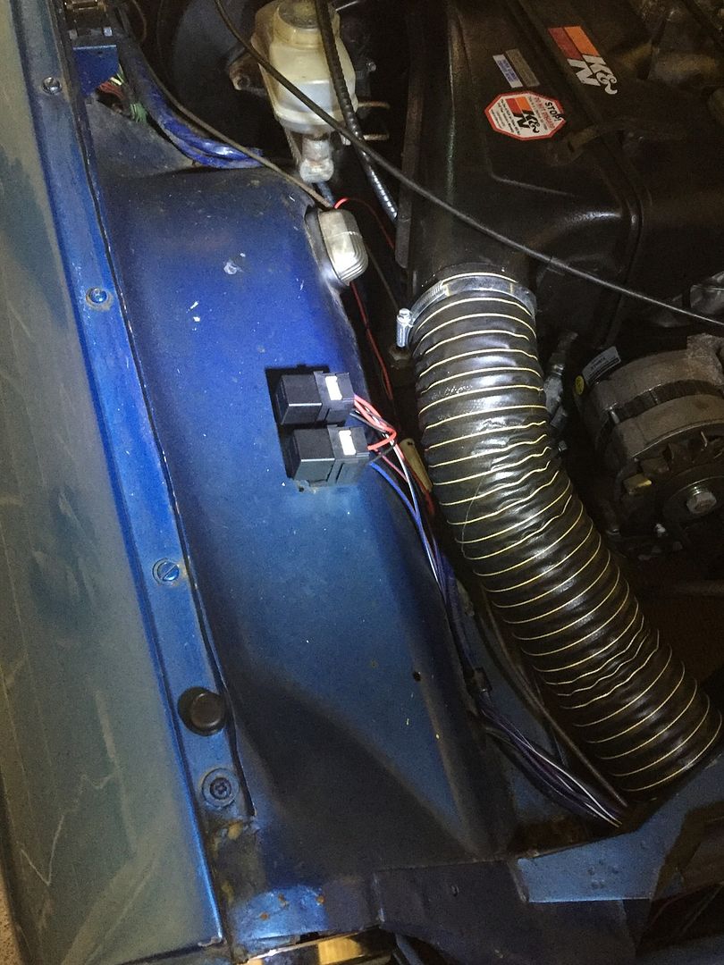
Have just sorted the problem. Actually, there wasn't a problem at all, it was just my incompetence / lack of knowledge. OK so the red / white ignition wire should be attached to the diagonally mounted spade terminal NOT to the smaller spade terminal marked "IGN". Confusing, but there you are. And the way to fasten the solenoid "eye" over the starter motor lever is to tie back the spring and top plate (which holds the eye against the lever when installed) with a piece of wire looped around the back of the solenoid piston. This wire keeps the "eye" open so you can slide it over the end of the lever and then, carefully remove the wire so the eye doesn't slip off the lever and, with the piston held carefully in place, slide the solenoid body over it and into position. Simples... So now I understand starter solenoids much better, and have a replacement one arriving in the post which I no longer need. Good to have a spare, probably. Anyway, the original reason for all this fuss was me installing headlight relays. These have reduced the voltage drop (cf. if the headlight circuit is all routed through the headlight switch) from 14.5-17% down to 5.6-7.1%, so I should have noticeably brighter lights. I also found that the mounting holes for the factory airbox, which was ditched in favour of the Lotus Excel airbox during the engine upgrade, are in a perfect position for the headlight relays, no new holes required.  I've read that upgrading sealed beam headlights to the H4 halogen type is a very common upgrade for classic cars, best done in combination with the installation of headlight relays. Looking at the GT parts manual, the oem headlights are described as "Q1V H4", so perhaps JML decided to use install the brighter lights but did not bother with the relays?
|
|||||||||||||
| ||||||||||||||
| Posted: 02-07-2016 07:44 am |
|
3rd Post |
|
Esprit2 Member
|
NigelK wrote:OK so the red / white ignition wire should be attached to the diagonally mounted spade terminal NOT to the smaller spade terminal marked "IGN". Confusing, but there you are. (Snip)...It's not really all that confusing once you understand the real meaning of 'IGN'. When the White-Red wire from the ignition switch energizes the solenoid, it also closes a second internal contact that sends 12 volts (full system voltage) to the smaller 'IGN' spade terminal. The attached wire feeds that voltage to the IGNition coil's (+) terminal. That by-passes the ballast resistor in order to feed higher voltage to the coil for a hotter spark during engine start. The hot spark only lasts as long as the starter is operated, so the coil doesn't over-heat. 'IGN' does not mean 'from' the ignition 'switch', it means 'TO' the ignition 'coil'. NigelK wrote: Anyway, the original reason for all this fuss was me installing headlight relays. These have reduced the voltage drop (cf. if the headlight circuit is all routed through the headlight switch) from 14.5-17% down to 5.6-7.1%, so I should have noticeably brighter lights. (Snip)...That's all well and good, and others have done similar mods. However, keep in mind that running a direct power feed to the headlights by-passes a significant power draw around whatever voltmeter/ ammeter the car may have (any car, not just JH), so the gauge will never monitor the power drawn by the lights. So when you look at the gauge, mentally add some for the lights. How much? I don't know, it's your circuit. Get a handle on it. If a short, or some other serious failure ever develops in the lighting circuit, you'll get no warning from the instruments. I'm not saying that's good or bad, just get your head around it and be alert for other symptoms that might give you a warning. Regards, Tim Engel Last edited on 02-07-2016 07:52 am by Esprit2 |
||||||||||||||
| |||||||||||||||
| Posted: 02-07-2016 09:48 am |
|
4th Post |
|
NigelK Member
|
Thanks Tim. Can you please expand on your second point? I'm no auto electrics expert, but looking at the GT wiring diagram it seems to me that the voltmeter is still wired in parallel with the headlight circuit, even with the relays added, so why wouldn't it still accurately measure the potential difference between the +ve post terminal on the starter solenoid and earth?
|
|||||||||||||
| ||||||||||||||
| Posted: 02-08-2016 05:17 am |
|
5th Post |
|
answerman Member
|
I have to disagree, Tim. That would be true of an ammeter, but since the JH has a voltmeter it's just a parallel connection across the entire system, like all of the components are. I would get the same voltage reading if I just connected a multimeter across the battery terminals as I do with the dash voltmeter (in fact, that's a good quick way to make sure your charging system is working... measure across the battery when the car's not running (should be 12v) and then when it's running (should be 13.5 to 14v).
|
||||||||||||||
| |||||||||||||||
| Current time is 03:42 pm | |
| > Jensen Healey & Jensen GT Tech > Electrical & Instruments > Starter Solenoid | Top |