| ||||
| ||||
| Moderated by: Greg Fletcher | Page:   ... 2 3 4 5 6 7 8 9 ... 2 3 4 5 6 7 8 9   |
|
|||||||||||||
| 16173 will be entering project status... | Rating: 
|
| Author | Post |
|---|
| Posted: 10-22-2015 02:31 am |
|
121st Post |
|
Arvin Appelman Member
|
When you install the seal make sure you hold it back aprox. 0.100" or it will leak like a sieve.
|
||||||||||||||
| |||||||||||||||
| Posted: 10-22-2015 07:36 pm |
|
122nd Post |
|
answerman Member
|
Thanks for the input, guys. Still haven't gotten an answer on the size of the bell housing bolts as far as mounting to the stand. I guess I'll just pull a few and take them to the hardware store and match them up with longer ones. Otherwise, the engine is basically ready to come out: peripherals are all removed, and all that's holding it in are the bell housing bolts and the two motor mounts. Planning on pulling it on Saturday, and before going any further mounting it to the stand and taking it outside for a thorough degreasing... it's a mess!
|
|||||||||||||
| ||||||||||||||
| Posted: 10-28-2015 08:28 pm |
|
123rd Post |
|
answerman Member
|
Engine came out last weekend without too much hassle and is now sitting on/strapped to a workbench I built just for the occasion, since it became pretty obvious that I wasn't going to get at the rear main seal too easily while the engine was on a stand. It's a gunky, goopy, oily mess, as expected. The inside of the bell housing is covered in oil and gunk (though the clutch and flywheel are surprisingly clean). To pull the engine, the approach I took was to unbolt the exhaust manifold from the engine (MUCH easier when the car is up in the air on a hoist, I have to say) and then lift the engine up and out, leaving the manifold in the car (since the entire exhaust system is welded together, there was no easy way to separate the manifold from the rest of the exhaust). We'll see how much luck I have getting it back together when the engine goes back in... I'll cross that bridge when I come to it. The short term goal at this point is to get the new rear main seal installed, and then I can put the engine properly on an engine stand for further work. To that end, I ordered the upper and lower gasket sets from Greg today. I'm not convinced I will go far enough into the engine to need all of them, but if I ordered just what I thought I was going to use my luck would be that I'd miss the one that would hold up the project while waiting for it to arrive.
|
||||||||||||||
| |||||||||||||||
| Posted: 11-02-2015 09:11 pm |
|
124th Post |
|
answerman Member
|
After a thorough degreasing and pressure washing of the engine, the new rear main seal was installed this weekend. It went pretty uneventfully. Tip: to get the spacing from the edge of the housing correct, I did a little measuring with my digital caliper and found that a "stack" of two CDs (I had some blank ones lying around) measure at .095" thick. They made a nice spacer when pressing the seal into place. The rear flange cleaned up nicely (no groove, just a mark where the old seal rode which cleaned up with a Scotchbrite pad and a little WD40). Honestly, centering the seal housing wasn't that much of an issue. The new seal fits much more tightly than the old one (which likely explains the leak) and it pretty much centered itself. As far as I can tell, it's centered to within a thousandth of an inch and I guess the only way to see if it was a success is to wait till the engine goes back in. Next step: removing the cams (forgot to bring my turkey baster to suck the oil out of the cam housings) and pull the head to send off to the machine shop to have them assess and do their magic.
|
|||||||||||||
| ||||||||||||||
| Posted: 11-06-2015 04:45 am |
|
125th Post |
|
answerman Member
|
Cam towers are removed (learned a bit about how to keep the shims in place in the process, only had two fall out but I know where they came from). The buckets and shims are bagged and labeled, and the head is removed. Seeing the tops of my pistons for the first time. Lots of carbon in there... Now, the head goes off to the machine shop, and I can turn my attention away from the engine for a while and start working on repairing the floors (the only thing I didn't address during the big stripdown and repaint a couple of years ago).
|
||||||||||||||
| |||||||||||||||
| Posted: 11-06-2015 04:45 am |
|
126th Post |
|
answerman Member
|
Whoops, duplicate post. I'll save this for the next time I have something to report. Last edited on 11-06-2015 04:46 am by answerman |
|||||||||||||
| ||||||||||||||
| Posted: 11-06-2015 01:37 pm |
|
127th Post |
|
Brett Gibson JH5 20497 Member
|
Mike are you having the cam tower O-Ring grove machined or is their already
|
||||||||||||||
| |||||||||||||||
| Posted: 11-06-2015 08:39 pm |
|
128th Post |
|
answerman Member
|
I am assuming it's already there (the head was removed about 7 years ago), I wasn't quite sure where to look for it. I will check later today. Hard to find pictures of this stuff.
|
|||||||||||||
| ||||||||||||||
| Posted: 01-08-2016 07:49 pm |
|
129th Post |
|
answerman Member
|
An update, because it's been a while. Just heard back from the machine shop: the head is in very good shape overall, nice and straight so no skimming necessary. His only concern was that the valve guides seemed a little loose, so since it's all apart I will be ordering a complete set of 16 valves, guides, and springs to be installed when it goes back together. Just going with the stock valves, not the stainless ones. I am going to go with the uprated springs from the club store, though. Not going to touch the block this time around since everything looks pretty good other than the usual carbon buildup. Question while I'm waiting to hear back from Greg: does anyone know if the valve guides in the club store are bronze, or steel? The ones Delta has are bronze, while the originals are steel, and my machine shop guy would prefer steel if available. Meanwhile, I've been plugging away at the floorpan repairs. It was a bit of a mess as I suspected. The PO had riveted some sheet metal over the existing floor and then covered the whole mess with some kind of sealant, almost a half inch thick in spots. I still have no idea what was used there. It has the consistency of a hard black plastic. Here's what the floors looked like after removal of seats and carpet, and the riveted in metal... 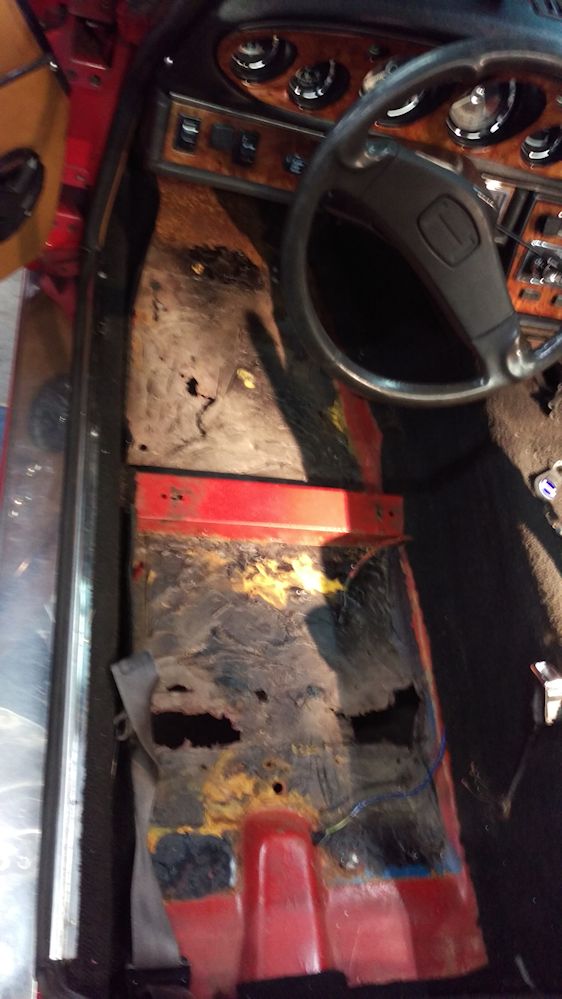 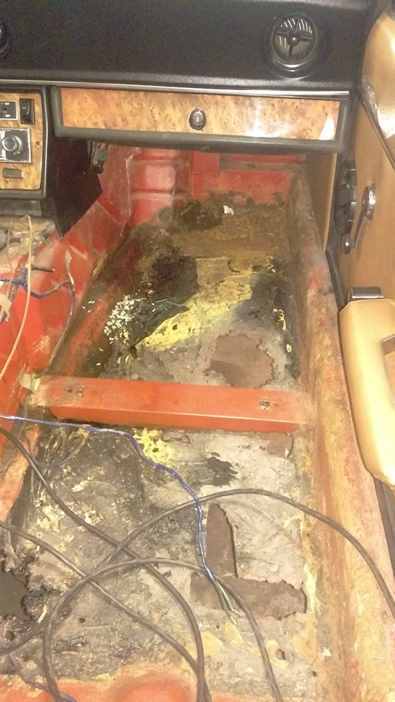 Anyway, it broke up easily when whacked with a hammer, and then the offending parts of the floor were cut out with a Sawzall and a pneumatic body saw. I looked into the replacement floor pans from Delta, but I just couldn't justify the cost. Since I have a metalworker in the family (my son) we decided that we could do it ourselves. It was an excuse to buy a couple of new tools: a 36" sheet metal brake, and a Milwaukee electric sheet metal shear which is the cat's pajamas for doing quick cutting work. So, the son and I created our own replacement floor. I went with 20 gauge cold rolled sheet steel (the original 19 gauge was not something I could find easily and 18 gauge seemed like overkill, it's not like I'm racing her). It was all bent by hand using a 36" sheet metal brake for the "square/straight" sections, and an anvil (an old section of railroad rail) and a hammer and torch to get the curves right near the gas pedal. Old school stuff I guess, and I'm learning as I go. A "during" shot of the drivers side: 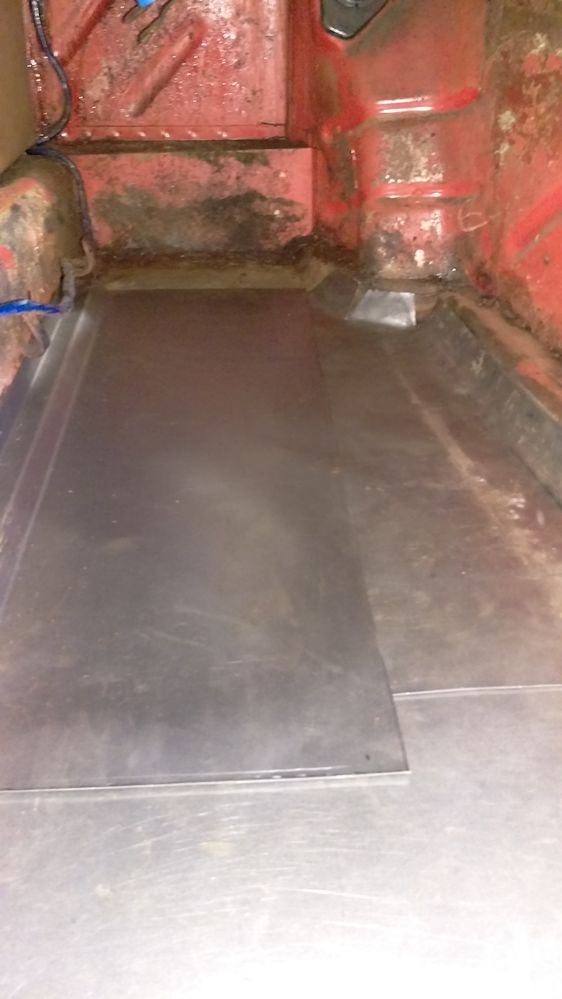 If you look closely you can see that there are 3 pieces to it: (1) the rear "under the seat" section which (from memory) is a basic rectangle about 22" wide and about 24" front to back, (2) the front left section which is a basic rectangle about 10" wide and about 26" front to back, and (3) the front right section which is about the same size but took a lot of cutting, heating, and hammering to get the curves into it. And finally, after it was all cut, heated, bent, hammered, and welded in place: 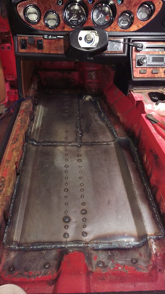 For the record: what you're seeing on the left inner sill isn't rust, it's old carpet adhesive. The whole thing came out of a piece of 20 gauge stock 24" x 60". I didn't roll any beads into it which may come back to haunt me, but it doesn't seem to be oil canning too badly Once the seat rails are welded back in that should give it a bit more side to side stability. Because of the channel that runs underneath front to back, there isn't more than 9' or so side to side that is unsupported so the rolled beads seemed like they wouldn't accomplish much. All that's left to do is get in there with a grinder and clean up the welds a bit. Then (waiting until after the passenger side is done), I'll need to fabricate new seat mounting rails, which should be the easiest part of all of this. The old ones look like someone chewed on them on the bottom edges. Now, on to the passenger side. That has its own set of issues: I cut out the old floor last night. More ugliness. It almost appears that it was replaced once before with very thin metal, the metal doesn't look anything like the drivers side (it actually has a texture to it, not smooth). And then, of course, this was all covered with the same black plastic filler. We're going to have to figure out the "box" at the firewall since the rust is actually creeping up the vertical there above the floor pan. Also, we will be addressing the rust underneath the battery tray... I can see through there into the car in a couple of spots. Hoping I can just remove the battery tray, patch in underneath, and then fabricate a new battery tray. This should be interesting... but the good news is that once this is done I can declare her rust free, or as rust free as they get, anyway. Last edited on 01-08-2016 08:23 pm by answerman |
||||||||||||||
| |||||||||||||||
| Posted: 05-02-2016 07:11 pm |
|
130th Post |
|
answerman Member
|
Ms. Jenavieve's engine is reassembled and back in. Last night I finally got to the point where I could fill up all the fluids and turn the key on the engine for the first time since last fall. Of course, no go. She's turning over but no fire. Tonight, I'll be troubleshooting more, but here's the current status: My timing light shows that #1 is firing right at 0 degrees (forgot to mark the Pertronix distributor position before the head came off, so I just set the engine at TDC and eyeballed the rotor to point at #1). Obviously not right, but you'd think it would be close enough to get a few puffs. Once I have more promising results, I'll adjust the distributor to the right position. Fuel pump (one of the Facet aftermarket ones) makes all sorts of clicky clicky noise so it's obviously got power, but I'm not convinced I've got gas at the carbs yet. I tried a shot of ether to see if that would catch, but nothing there either. Next step is to pull the fuel line from the T and find out if it's actually pumping. Oh, and the radiator sprung a leak sometime in the last few months while it was lying in the garage. Ordered one of the Champion aluminum replacements today since the old radiator had been repaired several times already, and I just can't see sinking any more money into a 42 year old radiator. It'll be weird to see that shiny aluminum in there but at least it'll work. Note to self, and anyone else who might be doing the same sort of work in the future: when you have the engine and transmission (4 speed) out, it would be a VERY GOOD IDEA to make sure you loosen the transmission fill plug while it's easily accessible. Don't wait till you put it back in the car like I did. I spent nearly an hour trying to get the plug loose (for all I know it was the first time it had been removed since 1974). Not much room to work in there. I finally ended up putting a jack under the transmission to support it, and then removing the nuts for the transmission support so that I could gently let the transmission down a couple of inches, enough to get a better angle on the plug with a box end wrench. Last edited on 05-02-2016 07:13 pm by answerman |
|||||||||||||
| ||||||||||||||
| Posted: 05-04-2016 07:42 am |
|
131st Post |
|
answerman Member
|
Kinda laughing at myself tonight. Two issues, one caused by impatience and the other by not paying attention for like the 12th time I've done this. End result: got Ms. J fired up tonight. Running a little lumpy but she is running. Can't do a whole lot more till my new radiator arrives... with the radiator leak I don't want to run her more than a few minutes. But I'm calling tonight a success (actually 2 successes, one having nothing to do with Jensen Healeys but I'll take my victories where I can). Now, what was I doing wrong last night? Well, regarding the fuel pump: I just needed to be more patient. After pulling the Pertronix wiring off the coil so it didn't get wrecked, I pulled the fuel line off the T and stuck a hose on it into a bucket. Turned the key to "on" and just let it click away... after about 40 seconds the clicking quieted and sure enough fuel flowed into the bucket. After having the system basically dry, apparently it takes a while to prime things back up. Connected the fuel line back to the T, turned the key on again and within seconds had fuel in the carbs. Good. So, now that I knew I had fuel: let's try timing again. I printed out Tim Engel's very comprehensive explanation of how to static time, which I ended up not using (you'll see why shortly). Just for fun, I went back and tried starting her again, and she caught a couple of times. Ooo! Very cool. So, I hooked up the timing light and had Mrs. Answerman turn the key while I watched... and the timing mark wasn't even visible. Huh? Ok, let's try the static again. I set the engine to TDC with a wrench, and pulled the distributor cap to see where the rotor was. Looked close, but retarded a bit. So I loosened it up and gave it a little twist to see if it made a difference. Tried starting her up and success! Barely running, but running. OK... let's hook up the timing light again. The mark is now visible, but about 30 degrees ATDC (obviously a guess, since the marks are BTDC but you get the idea). Headscratcher. I loosened the distributor up and gave it another twist, and started her up again. Better. Not perfect, but better. At least she was idling. Now I can take another look with the timing light... (this is where I admit to my not learning from previous experience) and the mark is right at 0 TDC. That can't be right... oh. Did I mention I hate my timing light? It has a knob on the back to set your advance and I always forget it's there. It is very loose, it turns if you just look at it, and of course that's cranked to something crazy like 40 degrees BTDC. So... turn the knob down to 0, try it again, and now things make more sense. It's idling at about 30 degrees BTDC. So, I gave the distributor a little more adjustment and now it's somewhere around 10 degrees BTDC which is in the ballpark of where I usually run it. Good enough for now till the radiator gets here and then I'll fine tune. Bonus (the unrelated thing): we have a couple of the Chinese 150cc scooters and they have been getting progressively harder and harder to start over the last year. Finally hit on a potential reason while Googling today (after cleaning the carbs, replacing the air filters, running Seafoam through them, etc): apparently, they are notorious for the valves requiring frequent adjustment. Nobody told me that. So, the reason I bring this up tonight is that if you want the polar opposite of valve adjustment on a Lotus 907, try it on a Chinese 150cc GY6 engine. Whole process took about 20 minutes per bike (and a good part of that was getting the plastic body bits off to get at the motor). 4 bolts and the valve cover comes off, loosen the locknut for the intake valve, back the adjustment screw out a few turns, stick a .005 feeler gauge in there, tighten the adjustment screw till you get a drag, tighten the locknut, pull the gauge out, and repeat for the exhaust valve. Easiest thing I've ever done, and they both start and idle instantly now. On both scooters the exhaust valve clearance was so tight that I don't know if it was ever closing. It's now on my scheduled maintenance list for the scooters.
|
||||||||||||||
| |||||||||||||||
| Posted: 10-03-2016 07:53 am |
|
132nd Post |
|
answerman Member
|
Wow, looking through old posts and realized I haven't posted in this thread in forever. I'll get some pics together and update soon, but the short version is that Ms. J got completely reassembled and had a very nice summer with very little repair required. Kind of nice for a change. Not planning on doing much with her this winter since, to be honest, there isn't much left to do. Plus, I acquired another project so Mrs. Answerman can have her own LBC, and this winter will be spent reassembling our "new" somewhat disassembled 1958 Nash Metropolitan convertible. Kind of the polar opposite of Ms. J: the JH is my "go fast" car while the Met will be more of a "looks nice, wins trophies at shows, everyone thinks it's cute, and if I can get it to go over 60MPH that's a bonus" car.
|
|||||||||||||
| ||||||||||||||
| Posted: 10-03-2016 09:13 am |
|
133rd Post |
|
UKJames Member
|
Glad to hear the JH is on the road again, I've enjoyed following your progress on this thread. There was a Nash Metropolitan in the next road to me, cute car. Interestingly it lived in the driveway of the house where they filmed 'Fahrenheit 451'. For those that remember it, it was the bungalow where the fireman lived.
|
||||||||||||||
| |||||||||||||||
| Posted: 05-10-2017 07:22 pm |
|
134th Post |
|
answerman Member
|
Another spring is here and Ms. J is on the road again. Did absolutely nothing with her this winter, as there wasn't really any reason to work on her and the Metropolitan kind of took up all my "throwing tools and cursing" time. But, the Met is finished, and I took it down to the British car clubhouse for our open house last week, and pulled Ms. J out as well since that's where she's been parked all winter. Then, they both came home. Here they are at our "mini-show", finally together.   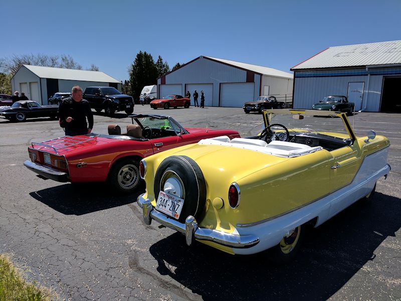  Small order of business for Ms. J over the next couple of weeks: install the new blue Gates Racing timing belt (it's been about 3 years and 10,000 miles) and at the same time replace her motor mounts with the Land Rover ones I bought almost a year ago to see if that helps with the whole "steering shaft through Delta 4-into-1 header" issue. The Rover mounts are a little bit thinner and should give me more leeway for adjustment so that the timing belt cover doesn't hit the bonnet. Once that's done, I'll be all ready to take her to Vermont for Jensen East. Last edited on 05-10-2017 07:30 pm by answerman |
|||||||||||||
| ||||||||||||||
| Posted: 05-10-2017 09:19 pm |
|
135th Post |
|
allstateguy Member
|
Great pix, glad you posted!
|
||||||||||||||
| |||||||||||||||
| Posted: 05-11-2017 10:42 pm |
|
136th Post |
|
redracer Member
|
Mike D'Olimpio at DELTA got some better engine mounts in that will likely fix your "height" adjustment. The former ones that were sold had to short a tread for shimming.
|
|||||||||||||
| ||||||||||||||
| Posted: 12-28-2017 05:31 pm |
|
137th Post |
|
answerman Member
|
It's still a project even though I've been driving her for over 5 years, right? So this is still an appropriate place to post? Anyway, over the next couple weekends I am FINALLY going to get around to installing the stuff I've been sitting on for way too long. It's time to get the blue Gates Racing timing belt installed: it's not doing any good having occupied space in the boot since last spring. Also, I need to install the new motor mounts (Land Rover) that I've had for almost 2 years. The logic behind this (ok, it works on paper) is as follows: I currently have the aftermarket motor mounts from Delta from about 3 years ago, in addition to the Delta 4 into 1 header. When I shim the motor mounts to allow clearance for the steering shaft through the header, it raises the engine up enough so that the timing belt cover contacts the underside of the bonnet. The temporary solution was to remove the top half of the cover, but in doing some measuring and playing with it I found that if I can actually lower the right/passenger side of the engine, I don't have to shim the left side as high since I can get more of a "twist" to the engine rotation. So, I'm going to try the Land Rover mounts since they are not quite as thick as the Delta mounts. I'm probably not going to put the cover back on anyway (the bottom half will come off when I do the timing belt change) but this seems to be the time to experiment with it. Finally, I need to replace the external O-ring on the distributor shaft to see if that solves my oil leak. What's happening is that I've got oil pooling in the little "pocket" on the block outside cylinder #2 (opposite the spark plug side), which then makes its way down to #3, #4, and out. I've verified that it's not the cam cover gasket or the head gasket, which basically leaves the distributor if I'm not missing something here. Hopefully the new O-ring will be the solution. That should be it for Jensen-related stuff for the winter: she'll then be ready for spring and I can move on to project "B" which is to (a) rebuild the front suspension on the Metropolitan, which is its own adventure (though it looks to be much simpler than the Jensen), and (b) install the 3.90:1 differential pumpkin that I picked up at British car show this fall (it's from an Austin-Healey Sprite) to replace the stock Metropolitan 4.22:1 pumpkin. Hopefully, I'll be able to get the Met up over 60MPH with this mod. Every little bit helps, right? Last edited on 12-28-2017 05:40 pm by answerman |
||||||||||||||
| |||||||||||||||
| Posted: 12-28-2017 06:09 pm |
|
138th Post |
|
redracer Member
|
Good luck with the "shimming". As for the distributor oil leak, it is much more likely from the seal on the spinning shaft itself, located below the weight plate. Removing the shaft is not too difficult; first, knock out the pin holding the drive gear on, being sure to mark which side goes on which side of the shaft(so you don't get your ignition timing 180 degree off upon reassembly). You can now knock th shaft up through the top of the distributor and see the seal(some early J-Hs did not even have a seal!!).
|
|||||||||||||
| ||||||||||||||
| Posted: 12-28-2017 06:23 pm |
|
139th Post |
|
answerman Member
|
I'll take a closer look at the distributor when I have it out, Bruce. It's a reasonably new distributor from Delta, bought it a little over 2 years ago, came with Pertronix preinstalled. So, I would hope it's not wear since it's only got about 3000 miles on it since installation. Honestly, the reason I'm suspecting the external O-ring is that I don't remember if it actually had one installed when I installed the distributor. Easy fix first, then I look further. Unless you have another idea of where the oil leak could be coming from.
|
||||||||||||||
| |||||||||||||||
| Posted: 12-28-2017 11:52 pm |
|
140th Post |
|
redracer Member
|
Almost forgot; while you're at it, shim the pressure relief valve. Knock out the split pin into the distributor shaft hole, and add just under 6mm to the spring(the washers that the cam cover bolts used are a perfect size--maybe 3 washers will do it)
|
|||||||||||||
| ||||||||||||||
| Current time is 05:54 pm | Page:   ... 2 3 4 5 6 7 8 9 ... 2 3 4 5 6 7 8 9   |
| > Jensen Healey & Jensen GT Tech > Projects > 16173 will be entering project status... | Top |